Creativo

در این وبلاگ به آموزش و یادگیری FPGA ها و زبان VHDL میپردازیم

۹ مطلب در فروردين ۱۳۹۹ ثبت شده است

اطلاعات تکمیلی

به نظر میرسد که در صنعت ایران بیشتر از FPGA های xilinx استفاده میشود.

نرم افزار vivado مدل های قدیمی تره fpga های xilinx را پشتیانی نمیکند.

برای استخراج test bench برای شبیه سازی میتوان از سایت های اینترنتی استفاده کرد که در این سایت ها با دادن کد vhdl کد test bench استخراج میشود.

بر روی fpga ها میتوان از سیستم عامل هایی مثل petalinux , yacto , git , freertos استفاده کرد.

در شبیه سازه FPGA شرکت ALTRA که نرم افزار Quartus است نیازی به نوشتن test Bench نیست و خوده نرم افزار این کار را به صورت اتوماتیک انجام میدهد.

در نرم افزار ISE و VIVADO خود شما باید test bench را بنویسید.

  • ۰ پسندیدم
  • ۰ نظر
    • creativo
    • يكشنبه ۱۰ فروردين ۹۹

    HOW TO USE CONSTANTS AND GENERIC MAP IN VHDL

    برای تغییر متغییر ها در کد استفاده میشود

    Creating modules is a great way to reuse code, but often you need the same module with smaller variations throughout your design. This is what generics and the generic map is for. It allows you to make certain parts of the module configurable at compile-time.

    Constants are used when we want to avoid typing the same value over and over again. They can be used for defining bit-widths of signal vectors at compile-time, and they can even be mapped to generic constants as well. Constants can be used in place of signals and variables anywhere in the code, but their values cannot be changed after compile-time.

    This blog post is part of the Basic VHDL Tutorials series.

    In the previous tutorial, we created a 4-input multiplexer module with a bus width of 8 bits. But what if we also need a similar MUX with a different bus width? Is the only solution to copy-paste the code into a new module, and change the numbers?

    Fortunately, no.

    It is possible to create constants in VHDL using this syntax:
    constant <constant_name> : <type> := <value>;

    Constants can be declared along with signals in the declarative part of a VHDL file, or it can be declared along with variables in a process.

    Constants can be passed into a module through the entity by using the generic keyword. The syntax for creating an entity for a module which accepts generic constants is:
    entity <entity_name> is
    generic(
    <entity_constant_name> : <type>;
    ...
    );
    port(
    <entity_signal_name> : in|out|inout <type>;
    ...
    );
    end entity;

    The syntax for instantiating a generic module in another VHDL file is:
    <label> : entity <library_name>.<entity_name>(<architecture_name>)
    generic map(
    <entity_constant_name> => <value_or_constant>,
    ...
    )
    port map(
    <entity_signal_name> => <local_signal_name>,
    ...
    );

    The final code for the generic MUX testbench:

    library ieee;
    use ieee.std_logic_1164.all;
    use ieee.numeric_std.all;

    entity T16_GenericMapTb is
    end entity;

    architecture sim of T16_GenericMapTb is

    constant DataWidth : integer := 8;

    signal Sig1 : signed(DataWidth-1 downto 0) := x"AA";
    signal Sig2 : signed(DataWidth-1 downto 0) := x"BB";
    signal Sig3 : signed(DataWidth-1 downto 0) := x"CC";
    signal Sig4 : signed(DataWidth-1 downto 0) := x"DD";

    signal Sel : signed(1 downto 0) := (others => '0');

    signal Output : signed(DataWidth-1 downto 0);

    begin

    -- An Instance of T16_GenericMux with architecture rtl
    i_Mux1 : entity work.T16_GenericMux(rtl)
    generic map(DataWidth => DataWidth)
    port map(
    Sel => Sel,
    Sig1 => Sig1,
    Sig2 => Sig2,
    Sig3 => Sig3,
    Sig4 => Sig4,
    Output => Output);

    -- Testbench process
    process is
    begin
    wait for 10 ns;
    Sel <= Sel + 1;
    wait for 10 ns;
    Sel <= Sel + 1;
    wait for 10 ns;
    Sel <= Sel + 1;
    wait for 10 ns;
    Sel <= Sel + 1;
    wait for 10 ns;
    Sel <= "UU";
    wait;
    end process;

    end architecture;
    The final code for the generic MUX module:

    library ieee;
    use ieee.std_logic_1164.all;
    use ieee.numeric_std.all;

    entity T16_GenericMux is
    generic(DataWidth : integer);
    port(
    -- Inputs
    Sig1 : in signed(DataWidth-1 downto 0);
    Sig2 : in signed(DataWidth-1 downto 0);
    Sig3 : in signed(DataWidth-1 downto 0);
    Sig4 : in signed(DataWidth-1 downto 0);

    Sel : in signed(1 downto 0);

    -- Outputs
    Output : out signed(DataWidth-1 downto 0));
    end entity;

    architecture rtl of T16_GenericMux is
    begin

    process(Sel, Sig1, Sig2, Sig3, Sig4) is
    begin

    case Sel is
    when "00" =>
    Output <= Sig1;
    when "01" =>
    Output <= Sig2;
    when "10" =>
    Output <= Sig3;
    when "11" =>
    Output <= Sig4;
    when others => -- 'U', 'X', '-', etc.
    Output <= (others => 'X');
    end case;

    end process;

    end architecture;

  • ۰ پسندیدم
  • ۰ نظر
    • creativo
    • جمعه ۸ فروردين ۹۹

    How to use Port Map instantiation in VHDL

    .برای کپسوله کردن کد ها و ساخت ماژول برای ساده سازی در طراحی ها استفاده میشود

    A module is a self-contained unit of VHDL code. Modules communicate with the outside world through the entity. Port map is the part of the module instantiation where you declare which local signals the module’s inputs and outputs shall be connected to.

    In previous tutorials in this series we have been writing all our code in the main VHDL file, but normally we wouldn’t do that. We create logic with the purpose of using it in an FPGA or ASIC design, not for the simulator.

    A VHDL module created for running in a simulator usually has no input or output signals. It is entirely self-contained. That’s why the entity of our designs have been empty. There has been nothing between the entity tag and the end entity; tag.

    This blog post is part of the Basic VHDL Tutorials series.

    A module without any input or output signals cannot be used in a real design. Its only purpose is to allow us to run VHDL code in a simulator. Therefore it is referred to as a testbench. To simulate a module with input and output signals we have to instantiate it in a testbench.

    Modules and testbenches often come in pairs, and they are stored in different files. A common naming scheme is to call the testbench the module name with “Tb” appended, and to name the architecture “sim”. If the module is called “MyModule” the testbench will be called “MyModuleTb”. Consequently, the filenames become “MyModuleTb.vhd” and “MyModule.vhd”.

    Testbench/module naming scheme

    With the help of the testbench code we can verify that the module is working correctly in a simulation environment. The module being tested is commonly referred to a the device under test (DUT).

    Modules can also be instantiated within other modules. Partitioning the code into modules allows it to be instantiated multiple times. You can create several instances of a module within the same design, and it can be reused across many designs.

    The syntax for an entity with a port in VHDL is:
    entity <entity_name> is
    port(
    <entity_signal_name> : in|out|inout <signal_type>;
    ...
    );
    end entity;

    The syntax for instantiating such a module in another VHDL file is:
    <label> : entity <library_name>.<entity_name>(<architecture_name>) port map(
    <entity_signal_name> => <local_signal_name>,
    ...
    );

    The <label> can be any name, and it will show up in the hierarchy window in ModelSim. The <library_name> for a module is set in the simulator, not in the VHDL code. By default every module is compiled into the work library. The <entity_name> and <architecture_name> must match the module we are creating an instance of. Finally, each of the entity signals must be mapped to a local signal name.

    There are other ways to instantiate a module in VHDL, but this is the basic syntax for explicit instantiation.

    The final code for the MUX testbench:

    library ieee;
    use ieee.std_logic_1164.all;
    use ieee.numeric_std.all;

    entity T15_PortMapTb is
    end entity;

    architecture sim of T15_PortMapTb is

    signal Sig1 : unsigned(7 downto 0) := x"AA";
    signal Sig2 : unsigned(7 downto 0) := x"BB";
    signal Sig3 : unsigned(7 downto 0) := x"CC";
    signal Sig4 : unsigned(7 downto 0) := x"DD";

    signal Sel : unsigned(1 downto 0) := (others => '0');

    signal Output : unsigned(7 downto 0);

    begin

    -- An instance of T15_Mux with architecture rtl
    i_Mux1 : entity work.T15_Mux(rtl) port map(
    Sel => Sel,
    Sig1 => Sig1,
    Sig2 => Sig2,
    Sig3 => Sig3,
    Sig4 => Sig4,
    Output => Output);

    -- Testbench process
    process is
    begin
    wait for 10 ns;
    Sel <= Sel + 1;
    wait for 10 ns;
    Sel <= Sel + 1;
    wait for 10 ns;
    Sel <= Sel + 1;
    wait for 10 ns;
    Sel <= Sel + 1;
    wait for 10 ns;
    Sel <= "UU";
    wait;
    end process;

    end architecture;

    The final code for the MUX module:

    library ieee;

    use ieee.std_logic_1164.all;

    use ieee.numeric_std.all;


    entity T15_Mux is

    port(

        -- Inputs

        Sig1 : in unsigned(7 downto 0);

        Sig2 : in unsigned(7 downto 0);

        Sig3 : in unsigned(7 downto 0);

        Sig4 : in unsigned(7 downto 0);


        Sel  : in unsigned(1 downto 0);


        -- Outputs

        Output : out unsigned(7 downto 0));

    end entity;


    architecture rtl of T15_Mux is

    begin


        process(Sel, Sig1, Sig2, Sig3, Sig4) is

        begin


            case Sel is

                when "00" =>

                    Output <= Sig1;

                when "01" =>

                    Output <= Sig2;

                when "10" =>

                    Output <= Sig3;

                when "11" =>

                    Output <= Sig4;

                when others => -- 'U', 'X', '-', etc.

                    Output <= (others => 'X');

            end case;


        end process;


    end architecture;

    As we can see from the waveform, the multiplexer (MUX) module works as expected. The waveform is identical to the one from the previous tutorial which we created without using modules.

    Now there is a clear separation between the design module and the testbench. The module containing the MUX is what we intend to use in a design, and the testbench’s only purpose is to allow us to run it in a simulator. There is a process in the testbench that uses wait statements for creating artificial time delays in the simulation. The design module has no notion of time, it only reacts to external stimuli.

    We named the architecture of the testbench sim, for simulation. The architecture of the design module was named rtl, which stands for register-transfer level. These are just naming conventions. When you see a file with such a name, you immediately know whether it’s a testbench or a design module. Different companies may have different naming conventions.

    Input and output signals are specified in the entity of a module

    A module with no in/out signals is called a testbench, and it can only be used in a simulator

    A module with in/out signals can usually not be run directly in a simulator

    library ieee;
    use ieee.std_logic_1164.all;
    use ieee.numeric_std.all;
     
    entity T15_Mux is
    port(
        -- Inputs
        Sig1 : in unsigned(7 downto 0);
        Sig2 : in unsigned(7 downto 0);
        Sig3 : in unsigned(7 downto 0);
        Sig4 : in unsigned(7 downto 0);
     
        Sel  : in unsigned(1 downto 0);
     
        -- Outputs
        Output : out unsigned(7 downto 0));
    end entity;
     
    architecture rtl of T15_Mux is
    begin
     
        process(Sel, Sig1, Sig2, Sig3, Sig4) is
        begin
     
            case Sel is
                when "00" =>
                    Output <= Sig1;
                when "01" =>
                    Output <= Sig2;
                when "10" =>
                    Output <= Sig3;
                when "11" =>
                    Output <= Sig4;
                when others => -- 'U', 'X', '-', etc.
                    Output <= (others => 'X');
            end case;
     
        end process;
     
    end architecture;
  • ۰ پسندیدم
  • ۰ نظر
    • creativo
    • جمعه ۸ فروردين ۹۹

    HOW TO USE A CASE-WHEN STATEMENT IN VHDL

    اصول کار multiplexer ها توضیح داده شود

    The Case-When statement will cause the program to take one out of multiple different paths, depending on the value of a signal, variable, or expression. It’s a more elegant alternative to an If-Then-Elsif-Else statement with multiple Elsif’s.

    Other programming languages have similar constructs, using keywords such as a switch, case, or select. Among other things, Case-When statements are commonly used for implementing multiplexers in VHDL. Continue reading, or watch the video to find out how!

    This blog post is part of the Basic VHDL Tutorials series.

    The basic syntax for the Case-When statement is:
    case <expression> is
    when <choice> =>
    code for this branch
    when <choice> =>
    code for this branch
    ...
    end case;

    The <expression> is usually a variable or a signal. The Case statement may contain multiple when choices, but only one choice will be selected.

    The <choice> may be a unique value like "11":
    when "11" =>

    Or it can be a range like 5 to 10:
    when 5 to 10 =>

    It can contain several values like 1|3|5:
    when 1|3|5 =>

    And most importantly, the others choice. It is selected whenever no other choice was matched:
    when others =>

    The others choice is equivalent to the Else branch in the If-Then-Elsif-Else statement.


    library ieee;
    use ieee.std_logic_1164.all;
    use ieee.numeric_std.all;

    entity T14_CaseWhenTb is
    end entity;

    architecture sim of T14_CaseWhenTb is

    signal Sig1 : unsigned(7 downto 0) := x"AA";
    signal Sig2 : unsigned(7 downto 0) := x"BB";
    signal Sig3 : unsigned(7 downto 0) := x"CC";
    signal Sig4 : unsigned(7 downto 0) := x"DD";

    signal Sel : unsigned(1 downto 0) := (others => '0');

    signal Output1 : unsigned(7 downto 0);
    signal Output2 : unsigned(7 downto 0);

    begin

    -- Stimuli for the selector signal
    process is
    begin
    wait for 10 ns;
    Sel <= Sel + 1;
    wait for 10 ns;
    Sel <= Sel + 1;
    wait for 10 ns;
    Sel <= Sel + 1;
    wait for 10 ns;
    Sel <= Sel + 1;
    wait for 10 ns;
    Sel <= "UU";
    wait;
    end process;

    -- MUX using if-then-else
    process(Sel, Sig1, Sig2, Sig3, Sig4) is
    begin

    if Sel = "00" then
    Output1 <= Sig1;
    elsif Sel = "01" then
    Output1 <= Sig2;
    elsif Sel = "10" then
    Output1 <= Sig3;
    elsif Sel = "11" then
    Output1 <= Sig4;
    else -- 'U', 'X', '-' etc.
    Output1 <= (others => 'X');
    end if;

    end process;

    -- Equivalent MUX using a case statement
    process(Sel, Sig1, Sig2, Sig3, Sig4) is
    begin

    case Sel is
    when "00" =>
    Output2 <= Sig1;
    when "01" =>
    Output2 <= Sig2;
    when "10" =>
    Output2 <= Sig3;
    when "11" =>
    Output2 <= Sig4;
    when others => -- 'U', 'X', '-', etc.
    Output2 <= (others => 'X');
    end case;

    end process;

    end architecture;

    First, we created a process using If-Then-Elsif-Else that would forward one of the signals Sig1, Sig2, Sig3, or Sig4, based on the value of the selector signal Sel.

    Then we created a process that did exactly the same, using the Case-When statement. We can see from the waveform that the output signals from the two processes, Output1 and Output2, behave exactly the same.

    In our example, the Sel signal has only four legal values. But if there had been a higher number of possibilities, we can easily see that the Case-When statement can help making code more readable. This is the preferred way of creating such a component by most VHDL designers.

    Understanding of the multiplexer was the bonus point of this exercise. Multiplexers, or MUX’s for short, are central components in digital design. It is simply a switch that selects one of several inputs, and forwards it to the output.

    This is an illustration of how our MUX forwards the selected input signal:
    mux
    We used the others clause to catch all values of Sel which were not ones or zeros. As we learned in the std_logic tutorial, these signals can have a number of values which are not '0' or '1'. It’s good design practice to deal with these values by outputting 'X'. This indicates an unknown value on this signal, and it will be visible in downstream logic as well.

    We can see from the waveform that when the Sel signal turned red, Output1 and Output2 also changed to "XX". This is when others => in action.

    Additionally, the console output in ModelSim shows a warning because of the Sel signal being set to "UU". The “** Warning: NUMERIC_STD.”=”: metavalue detected, returning FALSE” messages appear at 50 ns simulation time, which is exactly when the signals turn red.

    Case-When can be used instead of multiple If-Then-Elsif statements
    The when others => can be used to implement a default choice
    Multiplexers are preferably created using Case-When statements

  • ۰ پسندیدم
  • ۰ نظر
    • creativo
    • جمعه ۸ فروردين ۹۹

    HOW TO CREATE A CONCURRENT STATEMENT IN VHDL

    A concurrent statement in VHDL is a signal assignment within the architecture, but outside of a normal process construct. The concurrent statement is also referred to as a concurrent assignment or concurrent process.

    When you create a concurrent statement, you are actually creating a process with certain, clearly defined characteristics. Concurrent statements are always equivalent to a process using a sensitivity list, where all the signals to the right of the signal assignment operator are on the sensitivity list.

    These shorthand notation processes are useful when you want to create simple logic which results in the assignment of a single signal. Instead of typing out a full process construct with sensitivity lists and all of that, you can simply assign to the target signal directly in the architecture.

    When used correctly, the intention of the code will still be pretty clear. No need to create a process for every single bit you want to flip.

    library ieee;

    use ieee.std_logic_1164.all;

    use ieee.numeric_std.all;


    entity T13_ConcurrentProcsTb is

    end entity;


    architecture sim of T13_ConcurrentProcsTb is


        signal Uns :  unsigned(5 downto 0) := (others => '0');

        signal Mul1 : unsigned(7 downto 0);

        signal Mul2 : unsigned(7 downto 0);

        signal Mul3 : unsigned(7 downto 0);


    begin


        process is

        begin


            Uns <= Uns + 1;


            wait for 10 ns;

        end process;


        -- Process multiplying Uns by 4

        process is

        begin


            Mul1 <= Uns & "00";


            wait on Uns;


        end process;


        -- Equivalent process using sensitivity list

        process(Uns) is

        begin


            Mul2 <= Uns & "00";


        end process;


        -- Equivalent process using a concurrent statement

        Mul3 <= Uns & "00";


    end architecture;

    bit_shift_multiplication

    We can see from the waveform that Mul1, Mul2, and Mul3 behave exactly the same. This is because the concurrent statement and the two processes we created are equivalent.

    A concurrent statement works just like a process. All signals to the right of the <= are automatically added to the sensitivity list. This means that the signal to the left of the <= will be updated whenever one of the signals that are evaluated change.

    There are many ways to multiply numbers in VHDL. In this exercise we multiplied the Uns signal by 4, using bit shifting. All our signals are of unsigned type, meaning that they are interpreted by numbers. Appending a 0 to the right of a binary number is the same as multiplying it by 2.

    This is an illustration of what happens at the cursor in the waveform:

    bit_shift_multiplication

    • A concurrent statement is a signal assignment directly in the architecture region
    • Concurrent statements are equivalent to a process with all evaluated signals on the sensitivity list

    با & کردن 00 عمل ضرب در 4 انجام میشود.

    library ieee;
    use ieee.std_logic_1164.all;
    use ieee.numeric_std.all;
     
    entity T13_ConcurrentProcsTb is
    end entity;
     
    architecture sim of T13_ConcurrentProcsTb is
     
        signal Uns :  unsigned(5 downto 0) := (others => '0');
        signal Mul1 : unsigned(7 downto 0);
        signal Mul2 : unsigned(7 downto 0);
        signal Mul3 : unsigned(7 downto 0);
     
    begin
     
        process is
        begin
     
            Uns <= Uns + 1;
     
            wait for 10 ns;
        end process;
     
        -- Process multiplying Uns by 4
        process is
        begin
     
            Mul1 <= Uns & "00";
     
            wait on Uns;
     
        end process;
     
        -- Equivalent process using sensitivity list
        process(Uns) is
        begin
     
            Mul2 <= Uns & "00";
     
        end process;
     
        -- Equivalent process using a concurrent statement
        Mul3 <= Uns & "00";
     
    end architecture;
  • ۰ پسندیدم
  • ۰ نظر
    • creativo
    • جمعه ۸ فروردين ۹۹

    How to use Signed and Unsigned in VHDL

    The signed and unsigned types in VHDL are bit vectors, just like the std_logic_vector type. The difference is that while the std_logic_vector is great for implementing data buses, it’s useless for performing arithmetic operations.

    If you try to add any number to a std_logic_vector type, ModelSim will produce the compilation error: No feasible entries for infix operator “+”. This is because the compiler doesn’t know how to interpret this collection of bits that the vector is.

    This blog post is part of the Basic VHDL Tutorials series.

    We must declare our vector as signed or unsigned for the compiler to treat it as a number.

    The the syntax for declaring signed and unsigned signals is:
    signal <name> : signed(<N-bits> downto 0) := <initial_value>;
    signal <name> : unsigned(<N-bits> downto 0) := <initial_value>;

    Just like with std_logic_vector, the ranges can be to or downto any range. But declaring signals with other ranges than downto 0 is so uncommon, that spending any more time on the subject would only serve to confuse us. The initial value is optional, by default it’s 'U' for all bits.

    We have already been using the integer type for arithmetic operations in previous tutorials. So why do we need the signed and unsigned types? For most, digital designers like to have more control of how many bits a signal actually uses.

    Also, signed and unsigned values wrap around, while the simulator will throw a run-time error if an integer is incremented beyond bounds. Finally, signed and unsigned can have other values like 'U' and 'X', while integers can only have number values. These meta-values can help us discovering errors in our design.

    library ieee;
    use ieee.std_logic_1164.all;
    use ieee.numeric_std.all;

    entity T12_SignedUnsignedTb is
    end entity;

    architecture sim of T12_SignedUnsignedTb is

    signal UnsCnt : unsigned(7 downto 0) := (others => '0');
    signal SigCnt : signed(7 downto 0) := (others => '0');

    signal Uns4 : unsigned(3 downto 0) := "1000";
    signal Sig4 : signed(3 downto 0) := "1000";

    signal Uns8 : unsigned(7 downto 0) := (others => '0');
    signal Sig8 : signed(7 downto 0) := (others => '0');

    begin

    process is
    begin

    wait for 10 ns;

    -- Wrapping counter
    UnsCnt <= UnsCnt + 1;
    SigCnt <= SigCnt + 1;

    -- Adding signals
    Uns8 <= Uns8 + Uns4;
    Sig8 <= Sig8 + Sig4;

    end process;
    end architecture;

    signed_unsigned_waveform

    The radix of all signals in the waveform are set to hexadecimal so that we can compare them equally.

    In the wrapping counter example, we see that the signed and unsigned signals behave exactly the same way. Both UnsCnt and SigCnt start at 0, and are incremented one-by-one up to FF. Hex FF (decimal 255) is the largest value our 8-bit signals can hold. Therefore, the next increment wraps both of them back to 0.

    We created the two 4-bit signals Uns4 and Sig4, and gave them both an initial value of “1000”. We can see from the waveform that they are both just hex 8 (binary 1000).

    The last two 8-bit signals we created were Uns8 and Sig8. We can see from the waveform that their initial values are 0, as one would expect. But from there, they behave differently! Apparently, signed and unsigned types made a difference when adding two signals of different lengths.

    This is because of something known as sign extension. Adding positive or negative numbers stored in vectors of equal length, is the same operation in digital logic. This is because of how two’s complement works. If the vectors are of different lengths, the shortest vector will have to be extended.

    The unsigned 4-bit binary number “1000” is decimal 8, while the signed 4-bit number “1000” is decimal -8. The “1” at the left-most place of the signed number indicates that this is a negative number. Therefore, the two 4-bit signals are sign extended differently by the compiler.

    This is a visualization of how sign extension creates the differing values for the Uns8 and Sig8 signals:

    • Signals of signed and unsigned type are vectors that can be used in arithmetic operations
    • Signals of signed and unsigned type will overflow silently
    • Sign extension may create differing results for signed and unsigned types

  • ۰ پسندیدم
  • ۰ نظر
    • creativo
    • جمعه ۸ فروردين ۹۹

    HOW TO CREATE A SIGNAL VECTOR IN VHDL: STD_LOGIC_VECTOR

    The std_logic_vector type can be used for creating signal buses in VHDL. The std_logic is the most commonly used type in VHDL, and the std_logic_vector is the array version of it.

    While the std_logic is great for modeling the value that can be carried by a single wire, it’s not very practical for implementing collections of wires going to or from components. The std_logic_vector is a composite type, which means that it’s a collection of subelements. Signals or variables of the std_logic_vector type can contain an arbitrary number of std_logic elements.

    This blog post is part of the Basic VHDL Tutorials series.

    The syntax for declaring std_logic_vector signals is:
    signal <name> : std_logic_vector(<lsb> to <msb>) := <initial_value>;
    or
    signal <name> : std_logic_vector(<msb> downto <lsb>) := <initial_value>;
    where <name> is an arbitrary name for the signal and <initial_value> is an optional initial value. The <lsb> is the index of the least significant bit, and <msb> is the index of the most significant bit.

    The to or downto specifies the direction of the range of the bus, basically its endianess. Although both work equally well, it’s most common for VHDL designer to declare vectors using downto. Therefore, I recommend that you always use downto when you declaring bit vectors to avoid confusion.

    The VHDL code for declaring a vector signal that can hold a byte:
    signal MySlv : std_logic_vector(7 downto 0);

    The VHDL code for declaring a vector signal that can hold one bit:
    signal MySlv : std_logic_vector(0 downto 0);

    The VHDL code for declaring a vector signal that can hold zero bits (an empty range):
    signal MySlv : std_logic_vector(-1 downto 0);

    library ieee;
    use ieee.std_logic_1164.all;

    entity T11_StdLogicVectorTb is
    end entity;

    architecture sim of T11_StdLogicVectorTb is

    signal Slv1 : std_logic_vector(7 downto 0);
    signal Slv2 : std_logic_vector(7 downto 0) := (others => '0');
    signal Slv3 : std_logic_vector(7 downto 0) := (others => '1');
    signal Slv4 : std_logic_vector(7 downto 0) := x"AA";
    signal Slv5 : std_logic_vector(0 to 7) := "10101010";
    signal Slv6 : std_logic_vector(7 downto 0) := "00000001";

    begin

    -- Shift register
    process is
    begin

    wait for 10 ns;

    for i in Slv6'left downto Slv6'right + 1 loop
    Slv6(i) <= Slv6(i-1);
    end loop;

    Slv6(Slv6'right) <= Slv6(Slv6'left);

    end process;

    end architecture;

    std_logic_vector

    In this exercise we declared six std_logic_vector buses, each eight bits long (one byte).

    Signal Slv1 was declared without a initial value. The bus is seen having the value XX in the waveform screenshot. This is because the value that is displayed on the bus is in hexadecimals, and XX indicates a non-hex value. But when we expanded the bus in the waveform, we could see that the individual bits were indeed U’s.

    Signal Slv2 was declared using an initial value of all 0’s. Instead of specifying the exact value for each bit, we used (other => '0') in place of the initial value. This is known as an aggregate assignment. The important part is that it will set all bits in the vector to whatever you specify, no matter how long it is.

    Signal Slv3 was declared using an aggregate assignment to give all bits the initial value of 1. We can see FF displayed on this signal in the waveform, which is hex for eight 1’s.

    Signal Slv4 was declared with an initial value specified in hex, AA. Each hex digit is 4 bits long, therefore we must supply two digits (AA) for our vector which is 8 bits long.

    Signal Slv5 declares exactly the same initial value as Slv4, but now we specified it as the binary value 10101010. We can see from the waveform that both signals have the hex value AA.

    Signal Slv6 was declared with an initial value of all zeros, except for the rightmost bit which was '1'. We used a process to create a shift register from this signal. The shift register, as the name implies, shifts the contents of the vector one place to the left every 10 nanoseconds.

    Our process wakes up every 10 ns, and the For-Loop shifts all bits in the vector one place to the left. The final bit is shifted back into the first index by the Slv6(Slv6'right) <= Slv6(Slv6'left); statement. In the waveform we can see the '1' ripple through the vector.

    This is a visualization of how the '1' propagates through our shift register:

    shift_register

    By using the 'left' and 'right attributes, we made our code more generic. If we change the width of Sig6, the process will still work. It’s good design practice to use attributes where you can instead of hardcoding values.

    You may be wondering if there are more attributes that you can use, and there are. I won’t be talking more about them in this tutorial series, because I consider them to be advanced VHDL features.

    N-bit vectors should be declared using std_logic_vector(N-1 downto 0)
    A vector can be assigned as a whole or bits within it can be accessed individually
    All bits in a vector can be zeroed by using the aggregate assignment (others => '0')
    Code can be made more generic by using attributes like 'left and 'right

    از attribute برای تغییر پارامتر ها در کد استفاده میشود.

    ارزش بیت ها در کد متفاوت است MSB و LSB

  • ۰ پسندیدم
  • ۰ نظر
    • creativo
    • جمعه ۸ فروردين ۹۹

    چطوری از STD_logic استفاده کنیم.

    چطوری از STD_logic  استفاده کنیم.


    The most common type used in VHDL is the std_logic. Think of this type as a single bit, the digital information carried by a single physical wire. The std_logic gives us a more fine-grained control over the resources in our design than the integer type, which we have been using in the previous tutorials.

    Normally, we want a wire in a digital interface to have either the value '1' or '0'. These two values are the only values that a bit, a binary digit, can have. But in reality, a physical digital signal can be in a number of states, which the std_logic type does a good job emulating. Therefore it is the most frequently used type in VHDL.

    The std_logic type can have the following values:

    This may seem like a lot of different states for a type that is supposed to model a single binary value. Don’t worry, we won’t be using all these types in this tutorial series. We will be using '1' and '0' of course. And we will also be seeing 'U' and 'X', which will help us spot errors in our design. The other values are advanced VHDL features which can be used for things like modeling communication with for example I2C devices, or for creating tri-state buses.

    If several processes are trying to write different values to a signal, we say that it has multiple drivers. If a std_logic signal has multiple drivers, it won’t be a compilation or run-time error, at least not in the simulator. That is because std_logic is a resolved type, meaning that its value will be determined by a resolution function.

    The value of a std_logic signal with two drivers will be determined based on this resolution table:

    ‘1’ Logic 1
    ‘0’ Logic 0
    ‘Z’ High impedance
    ‘W’ Weak signal, can’t tell if 0 or 1
    ‘L’ Weak 0, pulldown
    ‘H’ Weak 1, pullup
    ‘-‘ Don’t care
    ‘U’ Uninitialized
    ‘X’ Unknown, multiple drivers

    The waveform window in ModelSim after we pressed run, and zoomed in on the timeline:

    std_logic_in_modelsim_waveform

    The waveform with the cursor placed on the other part of the repeating signal cycleThe waveform with the cursor placed on the other part of the repeating signal cycle:

    The exercise demonstrated how the resolution function of VHDL works with the std_logic type. When working with digital logic it’s often more practical to study the timeline in a waveform rather than using printouts. Therefore we used the ModelSim waveform to check the signal values in this exercise.

    The first process and Signal1 is only used for changing the value that the third process is driving on Signal2 and Signal3.

    The second process, Driver A, will try to drive a 'Z' onto Signal2, and a '0' onto Signal3 constantly.

    The third process, Driver B, will alternate between driving '1' and 'Z' onto both Signal2 and Signal3.

    We see in the waveform screenshots that Signal1 is changing between '0' and '1', because there is only one process trying to drive this signal. We can also see that the multiple driver signals are resolved according to the resolution table posted in the VHDL code comments:


    std_logic_x_in_waveform

    Signal Driver A Driver B Result
    Signal2 ‘Z’ ‘Z’ ‘Z’
    Signal2 ‘Z’ ‘1’ ‘1’
    Signal3 ‘0’ ‘Z’ ‘0’
    Signal3 ‘0’ ‘1’ ‘X’

    • std_logic is the most common type used to hold a single bit value in VHDL
    • Think of a std_logic signal as a physical wire in our digital design
    • If multiple processes try to drive a std_logic signal, its value is determined by a resolution table

    library ieee;
    use ieee.std_logic_1164.all;

    entity T10_StdLogicTb is
    end entity;

    architecture sim of T10_StdLogicTb is

    signal Signal1 : std_logic := '0';
    signal Signal2 : std_logic;
    signal Signal3 : std_logic;

    begin

    process is
    begin

    wait for 10 ns;
    Signal1 <= not Signal1;

    end process;

    -- Driver A
    process is
    begin

    Signal2 <= 'Z';
    Signal3 <= '0';
    wait;

    end process;

    -- Driver B
    process(Signal1) is
    begin

    if Signal1 = '0' then
    Signal2 <= 'Z';
    Signal3 <= 'Z';
    else
    Signal2 <= '1';
    Signal3 <= '1';
    end if;

    end process;


    end architecture;

    U X 0 1 Z W L H
    U X X 1 1 1 1 1 X 1
    U X 0 X 0 0 0 0 X 0
    U U U U U U U U U U
    U X X X X X X X X X
    U X 0 1 Z W L H X Z
    U X 0 1 W W W W X W
    U X 0 1 L W L W X L
    U X 0 1 H W W H X H
    U X X X X X X X X

  • ۰ پسندیدم
  • ۰ نظر
    • creativo
    • جمعه ۸ فروردين ۹۹

    آموزش VHDL به زبان فارسی

    زبان VHDL زبان سخت افزاری که برای دستور به FPGA ها استفاده میشود.

    برای آموزش و یادگیری این زبان نیاز به یک سری اطلاعات از مدار منطقی است.

    دو شرکت بزرگ در دنیا به نام های ALTRA و Xilinx تولید کننده ی FPGA هستند.

    نرم افزار های شبیه سازی برای این دو شرکت به ترتیب Quartus و Xilinx ISE است.

    System Edition کامل ترین نسخه ی نرم افزار ISE است.

    یک زبان سخت افزاری دیگر هم به نام Verilog وجود دارد.

    منابع زیادی برای یادگیری این زبان سخت افزاری وجود دارد.

    FPGA ها معمولا برای پردازش های سریع و بلادرنگ استفاده میشوند.

    همزمان بهتر است که دانشی از زبان C و ++C داشته باشید چرا که برای برنامه نویسی MicroBlaze استفاده خواهد شد.

    MicroBlaze میکروکنترلری است که درون FPGA به صورت Soft Core قابل پیاده سازی است.


    نرم افزار های دیگر

    Xilinx Embedded Development Kit (EDK)

    Xilinx Software Development Kit (SDK)

    Xilinx Platform Studio (XPS)


    امکاناتی در نرم افزار متلب وجود دارد که میتوان با استفاده از ISE از آن ها استفاده کرد

    برای شبیه سازی باید در کد Test Bench کلاک حذف شود چون کلاکی وجود ندارد

    برای وارد کردن ورودی ها در TB به قسمت insert stimulus باید وارد شد

    برای تغییر میتوان از دستور wait for  استفاده کرد.

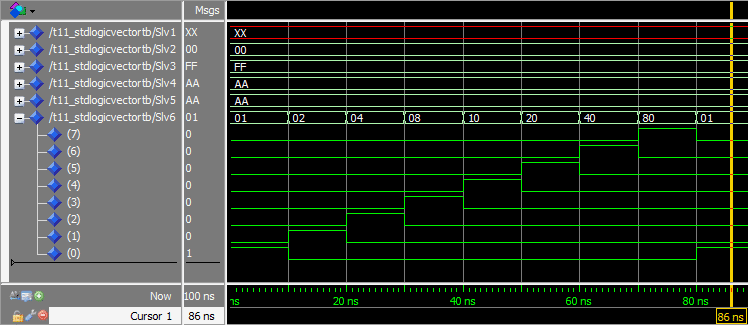
    توضیح انکدر وزن دار (مهم)

    نرم افزار ISim برای شبیه سازی 

     vivado نرم افزار جدیدی است که سری های جدیدتر FPGA های Xilinx را پشتیبانی میکند.

    AXI4 روش انتقالی است که توسط ARM و Xilinx استفاده می شود

    در بسیاری از کاربرد های FPGA ها پردازش سیگنال انجام میشود بنابراین بهتر است که با مفاهیم سیگنال و سیستم آشنایی داشته باشید.

     در شبیه سازی ها دقت داشته باشید در واقعیت هر یک از المان های استفاده شده در برنامه نویسی داری تاخیر هستند و هر یک با توجه با آن المان متغییر است (Propagation delay)


    -------------------------------------------------------------

     شروع به به کد زنی vhdl 

    hello world


    entity T01_HelloWorldTb is

    end entity;

    architecture sim of T01_HelloWorldTb is

    begin

        process is

        begin

            report "Hello World!";

            wait;

        end process;

    end architecture;


    این کد به شکل  sequentially اجرا می شود و هر خط به ترتیب از بالا به  پایین اجرا میشود.

    با زدن کلیک راست و وارد شدن به قسمت project setting  و فعال کردن display compile output  اطلاعات بیشتر نمایش داده خواهد شد

    برای اجرای دوباره باید تنظیمات شبیه ساز ریست شود

    -------------------------------------------------------------------

    دستور wait برای وایستادن برای همیشه استفاده میشود

    دستور wait for برای منتظر نگه ماندن برای یک زمان مشخص استفاده میشود.


    entity T02_WaitForTb is
    end entity;
     
    architecture sim of T02_WaitForTb is
    begin
     
        process is
        begin
            -- This is the start of the process "thread"
      
            report "Peekaboo!";
             
            wait for 10 ns;
             
            -- The process will loop back to the start from here
        end process;
     
    end architecture;


    کامنت گزاری با -- شروع میشود

     ----------------------------

    آمورش استفاده از دستور wait for


    The syntax of the wait for statement is:
    wait for <time_value> <time_unit>;
    where <time_value> is number and <time_unit> is one of the following time units:

    fs    femtoseconds
    ps    picoseconds
    ns    nanoseconds
    us    microseconds
    ms    milliseconds
    sec    seconds
    min    minutes
    hr    hours


    When working with digital logic that runs at MHz clock frequencies, you will usually be working with nanosecond increments.

    When we ran the code in the simulator, it printed “Peekaboo!” to the console every 10 ns. Because this is a simulation, the report statement takes zero time, and so does the looping.


    -------------------------------------------------------------

     آموزش استفاده از Loop و خارج شدن از آن در زبان VHDL

    entity T03_LoopTb is
    end entity;
     
    architecture sim of T03_LoopTb is
    begin
     
        process is
        begin
      
            report "Hello!";
             
            loop
                report "Peekaboo!";
                exit;
            end loop;
             
            report "Goodbye!";
            wait;
             
        end process;
     
    end architecture;


    The loop statement implements an infinite loop
    The exit statement will break out of any loop

    The process thread will pause at wait for for the exact specified time
    All statements other than wait statements take zero simulation time


    -----------------------------------------------------------

    آموزش استفاده از for loop 


    The syntax of the For-Loop is:

    for <c> in <r> loop
    end loop;
    The <c> is an arbitrary name for a constant that will available inside of the loop. The <r> is a range of integers or enumerated values which the loop will iterate over. An integer range can be either incrementing or decrementing.

    The VHDL code for an incrementing range including all 10 numbers from 0 to 9:

    0 to 9
    The VHDL code for a decrementing range including all 10 numbers from 9 to 0:

    9 downto 0
    The VHDL code for a range including only the number 0:

    0 to 0
    The VHDL code for an empty range that doesn’t have any numbers at all:

    0 to -1


    entity T04_ForLoopTb is
    end entity;
     
    architecture sim of T04_ForLoopTb is
    begin
     
        process is
        begin
     
            for i in 1 to 10 loop
                report "i=" & integer'image(i);
            end loop;
            wait;
             
        end process;
     
    end architecture;


    Not totally unexpectedly our For-Loop iterated ten times before terminating. The value of i is printed to the simulator console ten times at simulation time 0. There’s no wait statement inside of the loop, and therefore the loop takes zero time to complete. Finally, the program goes into an infinite pause on the wait;.

    We learned how to convert an integer to a string by using integer'image(), and we used the & character to join the two strings together.


    The For-Loop can iterate over an incrementing or decrementing integer range
    An incrementing range is denoted by to, and a decrementing range by downto
    An integer can be converted to a string by using integer'image()
    Two strings can be joined by using the string concatenation character &


    ----------------------------------------------

    آموزش while

    گزاشتن شرط برای اجرای یک دستور

    برای این که یک متغییر مقدار دهیم از =: استفاده میکنیم

    برای تعریف متغییر بین process is و  begin آن را تعریف میکنیم به اسم variable و سپس نوع آن و سپس مقدار اولیه برای آن در نظر میگیریم

    entity T05_WhileLoopTb is
    end entity;

    architecture sim of T05_WhileLoopTb is
    begin

    process is
    variable i : integer := 0;
    begin

    while i < 10 loop
    report "i=" & integer'image(i);
    i := i + 2;
    end loop;
    wait;

    end process;

    end architecture;

    توضیحات

    ساختار loop

    The syntax of the While-Loop is:

    while <condition> loop
    end loop;


    The <condition> is a boolean true or false. It can also be an expression which evaluates to true or false. The condition is evaluated before every iteration of the loop, and the loop will continue only if the condition is true.

    مثال

    Example expression which is true if i is less than 10:

    i < 10
    Example expression which is true if i is not 10:

    i /= 10
    Example expression which is true if i is greater than or equal to 0, and less than 28=256:

    i >= 0 and i < 2**8;


    Relational operators:

    عملگرها

    = equal
    /= not equal
    < less than
    <= less than or equal
    > greater than
    >= greater than or equal


    Logical operators:

    عملگرهای منطقی

    not a         true if a is false
    a and b      true if a and b are true
    a or b        true if a or b are true
    a nand b      true if a or b is false
    a nor b       true if a and b are false
    a xor b       true if exactly one of a or b are true
    a xnor b     true if a and b are equal

    We created an integer variable i and gave it an initial value of 0. We used an expression in the While-Loop that is true as long as i is less than 10. Because we were incrementing i by 2 in each iteration, the last number that was printed out was 8.

    On the next iteration, the i < 10 evaluated to false, because 10 is not less than 10. After the loop terminated, the program hit the wait; where it paused infinitely.

    The While-loop will continue as long as the condition is true

    دستور loop  تا زمانی که شرط آن درست باشه اجرا میشه


    The condition is evaluated before every iteration of the While-Loop


    Variables may be declared and used within a process

    -------------

    entity و architecture در هر کد باید متناسب با آن باشد

    تفاوت سیگنال ها و متغییر ها

    متغییر ها (variables) برای طراحی الگوریتم داخل پروسه استفاده میشوند ولی قابلیت دسترسی به دنیای بیرونی را ندارند.

    In the previous tutorial we learned how to declare a variable in a process. Variables are good for creating algorithms within a process, but they are not accessible to the outside world. If a scope of a variable is only within a single process, how can it interact with any other logic? The solution for this is a signal.

    Signals are declared between the architecture <architecture_name> of <entity_name> is line and the begin statements in the VHDL file. This is called the declarative part of the architecture.

    طراحی سیگنال

    The syntax for declaring a signal is:
    signal <name> : <type>;

    A signal may optionally be declared with an initial value:
    signal <name> : <type> := <initial_value>;

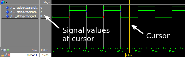
    We created a signal and a variable with the same initial value of 0. In our process we treated them in the exact same way, yet the printouts reveal that they behaved differently. First we saw that the assignment to a variable and a signal has a different notation in VHDL. Variable assignment uses the := operator while signal assignment uses the <= operator.

    MyVariable behaves as one would expect a variable to behave. In the first iteration of the loop it is incremented to 1, and then to 2. The last printout from the first iteration shows that its value is still 2, as we would expect.

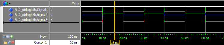
    MySignal behaves slightly different. The first +1 increment doesn’t seem to have any effect. The printout reveals that its value is still 0, the initial value. The same is true after the second +1 increment. Now the value of MyVariable is 2, but the value of MySignal is still 0. After wait for 10 ns; the third printout shows that the value of MySignal is now 1. The subsequent printouts follow this pattern as well.

    What is this sorcery? I will give you a clue, the wait for 10 ns; has something to do with it. Signals are only updated when a process is paused. Our process pauses only one place, at wait for 10 ns;. Therefore, the signal value changes only every time this line is hit. The 10 nanoseconds is an arbitrary value, it could be anything, even 0 nanoseconds. Try it!

    Another important observation is that event though the signal was incremented twice before the wait, its value only incremented once. This is because when assigning to a signal in a process, the last assignment “wins”. The <= operator only schedules a new value onto the signal, it doesn’t change until the wait. Therefore, at the second increment of MySignal, 1 is added to its old value. When it is incremented again, the first increment is completely lost.
    A variable can be used within one process while signals have a broader scope
    Variable assignment is effective immediately while signals are updated only when a process pauses
    If a signal is assigned to several times without a wait, the last assignment “wins”

    entity T06_SignalTb is
    end entity;

    architecture sim of T06_SignalTb is

    signal MySignal : integer := 0;

    begin

    process is
    variable MyVariable : integer := 0;
    begin

    report "*** Process begin ***";

    MyVariable := MyVariable + 1;
    MySignal <= MySignal + 1;

    report "MyVariable=" & integer'image(MyVariable) &
    ", MySignal=" & integer'image(MySignal);

    MyVariable := MyVariable + 1;
    MySignal <= MySignal + 1;

    report "MyVariable=" & integer'image(MyVariable) &
    ", MySignal=" & integer'image(MySignal);

    wait for 10 ns;

    report "MyVariable=" & integer'image(MyVariable) &
    ", MySignal=" & integer'image(MySignal);

    end process;

    end architecture;


     تغییر variable ها در همان لحظه اتفاق می افتد ولی singnal ها مقادیرشون وقتی به روز میشه که پروسس pause بشه 

     برای تعیین آدرس ها حتما دقت داشته باشید که ماژول به چه تعداد آدرس نیاز دارند و از آدرس و تعداد کم به زیاد آدرس دهی کنید

    برای دسترسی به اطلاعات حجیم میتوان از DMA و AXI استفاده کرد

    Petalinux is a tool you use to customise, build and deploy Embedded Linux solutions on Xilinx processing systems. It is an Embedded Linux Systems Development Kit that targets Xilinx SoC designs

    -------------------------

    How to use Wait On and Wait Until in VHDL

    برای دسترسی و آپدیت مقادیر سیگنال ها باید از دستور wait on و wait until استفاده میکنیم

    entity T07_WaitOnUntilTb is
    end entity;

    architecture sim of T07_WaitOnUntilTb is

    signal CountUp : integer := 0;
    signal CountDown : integer := 10;

    begin

    process is
    begin

    CountUp <= CountUp + 1;
    CountDown <= CountDown - 1;
    wait for 10 ns;

    end process;

    process is
    begin

    wait on CountUp, CountDown;
    report "CountUp=" & integer'image(CountUp) &
    " CountDown=" & integer'image(CountDown);

    end process;

    process is
    begin

    wait until CountUp = CountDown;
    report "Jackpot!";

    end process;


    end architecture;


    The Wait On statement will pause the process until one of the specified signals change:
    wait on <signal_name1>, <signal_name2> ...;

    The Wait Until statement will pause until an event causes the condition to become true:
    wait until <condition>;

    In fact, Wait On, Wait Until and Wait For can be combined:
    wait on <signal_name1> until <condition> for <time_value>;

    This example will pause for 10 nanoseconds, or until signal1 changes and signal2 is equal to signal3:
    wait on signal1 until signal2 = signal3 for 10 ns;

    ANALYSIS
    The first process increments the CountUp counter and decrements the CountDown counter. They are updated simultaneously. Although the signal assignments of the two signals are on different lines in the process, assigned signal values only become effective then the program hits a Wait statement. The process perform this operation at the start of the simulation, and then every 10 nanoseconds.

    The second process’ first line is wait on CountUp, CountDown;. The program will wait at this line until one or both of the signals change. As we can see from the printout, this happens at 0 ns simulation time when the counters are changed for the first time, and every time they change after that.

    The third process’ first line is wait until CountUp = CountDown;. The program will wake up every time one of the two signals change, just like the first process did. But it will only continue if the expression evaluates to true, otherwise it will go back to sleep. As we can see from the printout, “Jackpot!” is only printet once, at 40 ns when both counters have the same value.

    Wait On will wait until one of the signals change
    Wait Until will wake up if one of the signals change, but will only continue if the expression is true
    Wait On, Wait Until and Wait For can be combined
    ---------------

    هر دو زبان VHDL و verilog برای برنامه نویسی سخت افزار استفاده میشود

    زبان verilog بیشتر نزدیک به زیان های برنامه نویسی C و ++C است

    ممکن است مشکلاتی در اجرای کد به وجود آورد که فقط با پیاده سازی بر روی FPGA خودش را نشان میدهد

    بسته به درخواست صنعت و کشور این زبان ها انتخاب میشوند

    زبان VHDL به نسبت قید و بند بیشتری در برنامه نویسی را دارند.

    به نظر میرسد که زبان VHDL در ایران بیشتر مورد توجه قرار گرفته است.

    --------------------------------------------------

    استفاده از شرط ها

    The basic syntax is:

    if <condition> then
    elsif <condition> then
    else
    end if;

    The elsif and else are optional, and elsif may be used multiple times. The <condition> can be a boolean true or false, or it can be an expression which evaluates to true or false.

    Example expression which is true if MyCounter is less than 10:

    MyCounter < 10

    entity T08_IfTb is

    end entity;

    ---------------

    architecture sim of T08_IfTb is

    signal CountUp : integer := 0;

    signal CountDown : integer := 10;

    begin

    process is

    begin

    CountUp <= CountUp + 1;

    CountDown <= CountDown - 1;

    wait for 10 ns;

    end process;

    process is

    begin

    if CountUp > CountDown then

    report "CountUp is larger";

    elsif CountUp < CountDown then

    report "CountDown is larger";

    else

    report "They are equal";

    end if;

    wait on CountUp, CountDown;

    end process;

    end architecture;

    We gave CountDown an initial value of 10, and CountUp a value of 0. The first process changes both counter values at the exact same time, every 10 ns. When this happens, the second process is triggered because the program will always be waiting at the wait on CountUp, CountDown; line. The program will always be waiting there because the If-Then-Elsif-Else and the report statements consume zero simulation time.

    The If-Then-Elsif-Else statement will cause the program to take one of the three branches we created. The two first branches cover the cases where the two counters have different values. We could have dropped the single else, and used elsif CountUp = CountDown then which would have had the same result. But it is good design practice to cover all branches, and the else clause covers all intentional and unforeseen cases.

    As we can see from the printout, the second process takes one of the three branches every time the counters change.

    If-Then may be used alone or in combination with Elsif and Else.

    Expressions may contain relational and logical comparisons and mathematical calculations
    -------------

    ---------------

    چطوری SENSITIVITY LIST درست کنیم ؟

    You should always use a sensitivity list to trigger processes in production modules. Sensitivity lists are parameters to a process which lists all the signals that the process is sensitive to. If any of the signals change, the process will wake up, and the code within it is executed.

    We’ve already learned to use the wait on and wait until statements for waking up a process when a signal changes. However, to be honest, this isn’t how I write most of my processes.

    When writing VHDL code, the style of writing depends on whether or not the code is intended to be run only in a simulator. If I’m writing simulation code, like we have been doing in this tutorial series, I always use wait statements to control the processes. If I’m writing code that I intend to create a physical implementation of, I never use wait statements.

    The syntax for a process with a sensitivity list is:
    process(<signal1>, <signal2>, ..) is
    begin
        <main logic here>
    end process;

    An important quirk with the sensitivity list is that all signals that are read within the process must be on the sensitivity list. However, the simulator won’t inform you if you fail to add a signal to the sensitivity list, because it’s legal in the VHDL language. The problem is that if you fail to do this, the code will behave differently when synthesized and used in a physical implementation.

    In VHDL-2008, the keyword all is allowed to use instead of listing every signal. Unfortunately most synthesizing software don’t support this newer revision of the VHDL language.

    entity T09_SensitivityListTb is
    end entity;
     
    architecture sim of T09_SensitivityListTb is
     
        signal CountUp   : integer := 0;
        signal CountDown : integer := 10;
     
    begin
     
        process is
        begin
     
            CountUp   <= CountUp + 1;
            CountDown <= CountDown - 1;
            wait for 10 ns;
     
        end process;
     
        -- Process triggered using Wait On
        process is
        begin
     
            if CountUp = CountDown then
                report "Process A: Jackpot!";
            end if;
     
            wait on CountUp, CountDown;
     
        end process;
     
        -- Equivalent process using a sensitivity list
        process(CountUp, CountDown) is
        begin
     
            if CountUp = CountDown then
                report "Process B: Jackpot!";
            end if;
     
        end process;
     
    end architecture;


    We can see from the printouts that the two processes behave alike. That is because a process with a sensitivity list is by definition equivalent to a process with wait on at the end of the process.

    Processes with sensitivity lists are normally used in code that is intended to be synthesized. Such code is commonly referred to as register-transfer level (RTL) code. This is a convention, but there are good reasons for it. Although some wait on and wait until statements can be synthesized, it’s hard to know what kind of hardware it will create.

    • A process with a sensitivity list is equivalent to a process with wait on at the end
    • All signals that are being read within a process must be on the sensitivity list
    • Use wait statements in simulation code, and sensitivity lists in RTL code

    ----------------------

  • ۱ پسندیدم
  • ۰ نظر