چطوری از STD_logic استفاده کنیم.
The most common type used in VHDL is the std_logic. Think of this type as a single bit, the digital information carried by a single physical wire. The std_logic gives us a more fine-grained control over the resources in our design than the integer type, which we have been using in the previous tutorials.
Normally, we want a wire in a digital interface to have either the value '1' or '0'. These two values are the only values that a bit, a binary digit, can have. But in reality, a physical digital signal can be in a number of states, which the std_logic type does a good job emulating. Therefore it is the most frequently used type in VHDL.
The std_logic type can have the following values:
This may seem like a lot of different states for a type that is supposed to model a single binary value. Don’t worry, we won’t be using all these types in this tutorial series. We will be using '1' and '0' of course. And we will also be seeing 'U' and 'X', which will help us spot errors in our design. The other values are advanced VHDL features which can be used for things like modeling communication with for example I2C devices, or for creating tri-state buses.
If several processes are trying to write different values to a signal, we say that it has multiple drivers. If a std_logic signal has multiple drivers, it won’t be a compilation or run-time error, at least not in the simulator. That is because std_logic is a resolved type, meaning that its value will be determined by a resolution function.
The value of a std_logic signal with two drivers will be determined based on this resolution table:
| ‘1’ | Logic 1 |
| ‘0’ | Logic 0 |
| ‘Z’ | High impedance |
| ‘W’ | Weak signal, can’t tell if 0 or 1 |
| ‘L’ | Weak 0, pulldown |
| ‘H’ | Weak 1, pullup |
| ‘-‘ | Don’t care |
| ‘U’ | Uninitialized |
| ‘X’ | Unknown, multiple drivers |
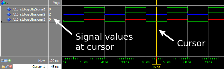
The waveform window in ModelSim after we pressed run, and zoomed in on the timeline:
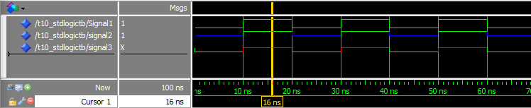
The waveform with the cursor placed on the other part of the repeating signal cycleThe waveform with the cursor placed on the other part of the repeating signal cycle:
The exercise demonstrated how the resolution function of VHDL works with the std_logic type. When working with digital logic it’s often more practical to study the timeline in a waveform rather than using printouts. Therefore we used the ModelSim waveform to check the signal values in this exercise.
The first process and Signal1 is only used for changing the value that the third process is driving on Signal2 and Signal3.
The second process, Driver A, will try to drive a 'Z' onto Signal2, and a '0' onto Signal3 constantly.
The third process, Driver B, will alternate between driving '1' and 'Z' onto both Signal2 and Signal3.
We see in the waveform screenshots that Signal1 is changing between '0' and '1', because there is only one process trying to drive this signal. We can also see that the multiple driver signals are resolved according to the resolution table posted in the VHDL code comments:
| Signal | Driver A | Driver B | Result |
|---|---|---|---|
| Signal2 | ‘Z’ | ‘Z’ | ‘Z’ |
| Signal2 | ‘Z’ | ‘1’ | ‘1’ |
| Signal3 | ‘0’ | ‘Z’ | ‘0’ |
| Signal3 | ‘0’ | ‘1’ | ‘X’ |
-
std_logicis the most common type used to hold a single bit value in VHDL - Think of a
std_logicsignal as a physical wire in our digital design - If multiple processes try to drive a
std_logicsignal, its value is determined by a resolution table
library ieee;
use ieee.std_logic_1164.all;
entity T10_StdLogicTb is
end entity;
architecture sim of T10_StdLogicTb is
signal Signal1 : std_logic := '0';
signal Signal2 : std_logic;
signal Signal3 : std_logic;
begin
process is
begin
wait for 10 ns;
Signal1 <= not Signal1;
end process;
-- Driver A
process is
begin
Signal2 <= 'Z';
Signal3 <= '0';
wait;
end process;
-- Driver B
process(Signal1) is
begin
if Signal1 = '0' then
Signal2 <= 'Z';
Signal3 <= 'Z';
else
Signal2 <= '1';
Signal3 <= '1';
end if;
end process;
end architecture;
| U | X | 0 | 1 | Z | W | L | H | – | |
|---|---|---|---|---|---|---|---|---|---|
| U | X | X | 1 | 1 | 1 | 1 | 1 | X | 1 |
| U | X | 0 | X | 0 | 0 | 0 | 0 | X | 0 |
| U | U | U | U | U | U | U | U | U | U |
| U | X | X | X | X | X | X | X | X | X |
| U | X | 0 | 1 | Z | W | L | H | X | Z |
| U | X | 0 | 1 | W | W | W | W | X | W |
| U | X | 0 | 1 | L | W | L | W | X | L |
| U | X | 0 | 1 | H | W | W | H | X | H |
| U | X | X | X | X | X | X | X | X | – |